Arc Welding and its different processes

Arc Welding:
The arc welding is a fusion welding process in which the welding heat is obtained from an electric arc struck between the work(or base metal) and an electrode. The temperature of the heat produced by the electric arc is of the order of 6000°C to 7000°C. Both the direct current (D.C) and alternating current(A.C) may be used for arc welding, but the direct current is preferred for most purposes. When the work is connected to the positive terminal of the D.C welding machine and the negative terminal to an electrode holder, the welding set up is said to have straight polarity. On the other hand, when work is connected to negative and the electrode to a positive terminal, then the welding set up is said to have reversed polarity. The straight polarity is preferable for some welds while for other welds reversed polarity should be used.
Following are the two types of arc welding depending upon the type of electrode:
(A): Un shielded arc welding:
When a large electrode or filler rod is used for welding, it is said to be un- shielded arc welding.
(B): Shielded arc welding:
When the welding rods coated with fluxing material are used, then it is called shielded arc welding.
Arc welding Processes:
The following are the various welding processes commonly used in engineering practice.
1: Carbon arc welding
In carbon arc welding, the welding heat is obtained from an electric arc between a carbon electrode and the work. In welding heavy plants, the additional metal is deposited in the weld from a filler rod.
2: Metal arc welding
In metal arc welding , the arc is produced between the metal electrode(also called filler rod) and the work piece. During the welding process, the metal electrode is melted by the heat of the arc and fused with the work piece. The temperature produced by the heat is about 2400° C to 2700° C.
3: Metallic inert gas (MIG) Arc welding:
In MIG welding , the electrode is consumable, the filler metal is deposited by the arc which is completely surrounded by an inert gas.
4: Tungsten inert gas(TIG) arc welding
In TIG welding, the heat is produced from an arc between the non consumable tungsten electrode and the work piece. The welding zone is shielded by an atmosphere of inert gas(such as helium or argon) supplied from a suitable source. The direct current with a straight polarity is used for welding copper alloys and stainless steel. Whereas the reversed polarity is used for magnesium. The alternating current is more versatile in welding for steel, cast iron, aluminum and magnesium.
5: Atomic hydrogen welding
In atomic hydrogen welding, the arc is obtained between two tungsten  electrodes (non consumable) while a stream of hydrogen passes by the arc and envelopes the welding zone.
6: Stud arc welding
It is a direct current arc welding process, and is used for welding metal studs to the flat metal surfaces.
7: Submerged arc welding
In submerged welding, the arc is produced between a bare metal electrode and the work piece. The submerged arc welding is mostly done on low carbon and alloy steels, but it may be used on many of the non-ferrous metals.
8: Thermit welding
In this welding, a mixture of iron oxide and aluminum known as thermit, is used. The mixture is ignited only at a temperature of about 1500°C. A major advantage of the thermit welding is that all parts of the weld section are molten at the same time and the weld cools almost uniformly. This results in a minimum problem with internal residual stresses. The thermit welding is often used in joining iron and steel parts that are too large to be manufactured, such as rails, trucks frames, locomotive frames, other large sections used on steam and rail roads, for stern frames, rubber frames etc. In steel mills, Thermit electric welding is employed to replace broken gear teeth, to weld new necks on rolls and pinions and to repair broken shears.

Electric Resistance Welding

Electric Resistance Welding
It is a type of pressure welding. It is used for joining pieces of sheet metal or wire. The welding heat is obtained at the location of the desired weld by the electrical resistance through the metal pieces to a relatively short duration, low voltage, high ampere electric current. The amount of current can be regulated by changing the primary turns of the transformer. When the area to be welded is sufficiently heated, the pressure varying from 25MPa to 55MPa is applied to the joining area by suitable electrodes until the weld is solid. The various types of electric resistance welding are as follows:
(1) Spot welding
It is used for welding lap joints, joining components made from plate material having 0.025 to 1.25 mm in thickness. The plate to be joined together are places between the two electrode tips of copper or copper alloy.
(2) Roll spot and seam welding
When the spot welds on two over lapping pieces of metal are spaced, the process of welding is known as roll spot welding. If the spot welds are sufficiently made close, then the process is called seam welding. This process is best for metal thickness ranging from 0.0.25 to 3 mm.
(3) Projection welding
It is similar to spot welding except that one of the metal pieces to be welded has projections on its surface at the points, Where the welds are to be made. In other words it is a multi spot welding process.
(4) Butt welding
The butt welding is of two type :
·        Upset butt welding
·        Flash butt welding
The upset butt welding is especially adopted to rods, pipes and many other components of uniform sections. The flash butt welding is extensively used in the manufacture of steel containers and in the welding of mild steel shanks to high speed drills and reamers.

Pattern and its types

“Pattern”- making, allowances and its types:
Pattern:
A pattern may be defined as a model of desired casting which when moulded in sand forms an impression called mould. The mould when filled with the molten metal forms casting after solidification of the poured metal. The quality and accuracy of casting depends upon the pattern making. The pattern may be made of wood, metal(cast iron, brass, aluminium and alloy steel.), plaster, plastics and wax.
Pattern Allowances:
A pattern is always made larger than the required size of the casting considering the various allowances. These are the allowances which are usually provided in a pattern.
1: shrinkage or contraction allowance:
The various metals used for casting contract after solidification in the mould. Since the contraction is different for different materials, therefore it will also differ with the form or type of metal.
2: Draft allowance
It is a taper which is given to all the vertical walls of the pattern for easy and clean withdraw of the pattern from the sand without damaging the mould cavity. It may be expressed in millimeters on a side or in degrees. The amount of taper varies with the type of patterns. The wooden patterns require more taper than metal patterns because of the greater frictional resistance of the wooden surfaces.
3: Finish or machining allowance
The allowance is provided on the pattern if the casting is to be machined. This allowance is given in addition to shrinkage allowance. The amount of this allowance varies from 1.6 to 12.5 mm which depends upon the type of the casting metal, size and the shape of the casting. The ferrous metals require more machining allowance than non ferrous metals.
4: Distortion or camber allowance
This allowance is provided on patterns used for casting of such design in which the contraction is not uniform throughout.
5: Rapping or shaking allowance
This allowance is provided in the pattern to compensate for the rapping of mould because the pattern is to be rapped before removing it from the mould.
Types of Patterns:
The common types of patterns are as follows:
1.     solid or single piece patterns
2.     split or two/multiple piece patterns
3.     match plate pattern
4.     cope and drag pattern
5.     loose piece pattern
6.     gated patterns
7.     sweep pattern
8.     skeleton pattern
9.     shell pattern
10. segmental pattern
11. follow board pattern
12. lagged up pattern
13. left and right hand pattern

Special Casting Processes

Special Casting Processes:
The sand moulds may be used for casting ferrous and non-ferrous metals, but these moulds can be used only once, because the mould is destroyed after the metal has solidified. This will increase the cost of production. The sand moulds also, can not maintain the tolerance and smooth surface finish. In order to meet these requirements, following casting method may be use:
1: Permanent Mould Casting
A casting made by pouring molten metal by gravity into a mould made of some metallic alloy or other material of permanence is known as permanent mould casting.
2: Slush Casting
The slush casting is a special application involving the used of  permanent mould. It is used for casting low melting temperature alloys. This method is only adopted for ornaments and toys of non-ferrous alloys.
3: Die Casting
The die casting (also known as pressure die casting) may be defined as that casting which uses the permanent mould(called die) and the molten metal is introduced into it by means of pressure, following are two type of die casting machines commonly used for die casting:
(a)  Hot chamber die casting machine
In a hot chamber die casting machine, the melting pot is an integral part of the machine. The molten metal is forced in the die cavity at pressure from 7 to 14 MPa. The pressure may be obtained by compressed air or by hydraulically operated plunger. The hot chamber die casting machine is use for casting zinc, tin, lead and other low casting melting alloys.
(b)  Cold chamber die casting machine
In a cold chamber die casting machine , the melting pot is usually separate from the machine and the molten metal is not transferred to injection mechanism by ladle. The pressure on the casting metal may vary from 21 to 210 MPa and in same cases may reach 700 MPa. This process is used for casting aluminum, magnesium, copper, brass alloys and other high melting alloys.
4: Centrifugal Casting
A casting process in which the molten metal is poured and allowed to solidify while the mould is revolving, is called centrifugal process. The casting produced under this centrifugal force is called centrifugal casting. This process is especially designed for casting of symmetrical shape. The ferrous and the non-ferrous metals can be obtained by this process. The casting produced by this process have dense and fine grained structure.
5: Investment Casting
It is also known as lost wax process or precision casting. The casting produced by this method are within very close tolerance(±0.05mm).
6: Shell Moulding Process
The shell moulding process is also called croning process. The shell cast part can be produced with dimensional tolerance of ±02 mm.

Moulding sand properties and its types

Moulding sand properties and its classification:
The moulding is a process of making a cavity or mould out of sand by means of a pattern. The molten metal is poured into the moulds to produce casting.
Properties of moulding sand
1: porosity or permeability
It is the property of sand which permits the steam and other gases to pass through the sand mould. The porosity of sand depends upon its grain size, grain shape, moisture and clay components are the moulding sand. If the sand is too fine, the porosity will be low.
2: Plasticity
It is that property of sand due to which it flows to all portions of the moulding box or flask. The sand must have sufficient plasticity to produce a good mould.
3: Adhesiveness
It is that properties of sand due to it adheres or cling to the sides of the moulding box.
4: Cohesiveness
It is the property of sand due to which the sand grains stick together during ramming. It is defined as the strength of the moulding sand.
5: Refractoriness
The property which enables it to resist high temperature of the molten metal without breaking down o r fusing.
Classification of Moulding sand according to their use:
1: Green sand
 The sand in its natural or moist state is called green sand. It is also called tempered sand. It is a mixture of sand with 20 to 30 percent clay, having total amount of water from 6 to 10 percent. The mould prepared with this sand is called green sand mould, which is used for small size casting of ferrous and non-ferrous metals.
2: Dry Sand
The green sand moulds when baked or dried before pouring the molten metal are called dry sand moulds. The sand of this condition is called dry sand. The dry sand moulds have greater strength, rigidity and thermal stability. These moulds used for large and heavy casting.
3: Loam Sand
A mixture of 50 percent sand grains and 50 percent clay is called loam sand. It is used for loam moulds of large grey iron casting.
4: Facing Sand
A sand which is used before pouring the molten metal, on the surface is called facing sand. It is specially prepared sand from silica sand and clay.
5: Backing or Floor Sand
A sand used to back up the facing sand and not used next to the pattern is called backing sand. The sand which have been repeatedly used may be employed for this purpose. It is also known as black sand due to its colour.
6: System Sand
A sand employed in mechanical sand preparation and handling system is called system sand. This sand has high strength, permeability and refractoriness.
7: Parting Sand
A sand employed on the faces of the pattern before the moulding is called parting sand. The parting sand consists of dried silica sand, sea sand or burnt sand.
8: Core Sand
The cores are defined as sand bodies used to form the hollow portions or cavities of desired shape and size in the casting. Thus the sand used for making these cores is called core sand. It is sometimes called oil sand. It is the silica sand mixed with linseed oil or any other oil as binder.


Casting Defects

Casting Defects:
The defects in a casting may be due to pattern and moulding box equipment, moulding sand, cores,gating system or molten metal. Some of the defects are:
1: Mould shift
It results in a mismatching of the top and the bottom parts of the casting , usually at the parting line.
2: Swell
It is an enlargement of the mould cavity by molten metal pressure resulting in localized or general enlargement of the casting.
3: Fins and Flash
These are thin projections of the metal not intended as a part of casting. These usually occurs at the parting line of the mould.
4: Sand Wash
It usually occurs near the in the gates as rough lumps on the surface of a casting.
5: Shrinkage
It is a crack or breakage in the casting on the surface of the work piece, which results from un equal contraction of the metal during solidification.
6: Hot Tear
It is an internal or external ragged discontinuously in the metal casting resulting just after the metal has solidified.
7: Sand Blow or Blow Hole
It is smooth depression on the outer surface of the casting work piece.
8: Honeycombing or Slag holes
These are smooth depression on the upper surface of the casting. They usually occur near the ingates.
9: Scabs
These are patches of sand on the upper surface of the casting component.
10: Cold Shut and Misruns
These happens when the mould cavity is not completely filled by the molten and insufficient material or metal.
11: Run-outs and Bust-outs
These permit drainage of the metal from the cavity and result in incomplete casting.

Drilling and parts of a twist drill

Drill or Drilling operation:
Drilling is the process of cutting or originating a round hole from the solid material. There are many ways of classifying drills. The tool(drill) and not the work piece is revolved and is fed into the material along its axis.
 For example , according to material, number and types of flutes, drill size , type of shank(straight or taper) and cutting point geometry etc. However the most common type of drill is the fluted drill shown in figure.

It is made from a round bar of tool material , and has three principles parts: the point, the body and the shank. The drill is held and rotated by its shank. The point comprises the cutting elements while the body guides the drill in the operation. The body of the drill has two helical grooves called “ flutes”. The flutes from the cutting surface and also assist in removing chips out of the drilled hole. The parts of twist drill are:
1: point:
The point is the cone shaped end and it does the cutting. It consists of the following:
(A)   dead center: It is the sharp edge at the extreme tip of the drill. This should always be the exact center of the drill.
(B)   Lips: these are the cutting edges of the drill.
(C)   Heel : It is the portion of the point back from the cutting edge.
2: Shank :
It is the portion of the drill by which it is clamped in the spindle. The shank may be either straight or tapered. Straight shank drills are used with a chuck. Tapered shank drills have self-holding tapes that fit directly into the drill press spindle. On the taper shank is the another term is used which is called tang. This fits into a slot in the spindles sleeve.
3: Body :
It is the portion between the point and the shank. The body consists of the following parts:
(A) Flutes :
Two or more spiral grooves that run the length of the drill body are called flutes. The flutes do four thing.
·        Help from the cutting edge of the drill point.
·        Curl the chip tightly for easier removal.
·        From channels through which chips can escape from the hole being drilled.
·        Allow the coolant and lubricant to get down to the cutting edge.
(B) Margin
It is the narrow strip extending back the entire length of the flute. It is the full diameter of the drill.
(C) Body Clearance:
It is the part of the drill body that has been reduced in order to cut down friction between the drill and the wall of the hole. 

Reamer and its types

Reamer:
A reamer is a rotating cutting tool generally of cylindrical shape which is used to enlarge and finish holes to accurate dimensions to previously formed hole. It is a multiple edge cutting tool having the cutting edge on its periphery.
Parts of Reamer:
A reamer consists of three mean parts:
1.     Fluted section
2.     Neck
3.     Shank
The fluted part consists of chamfer, starting taper, sizing section and back taper length. Chamfer length or bevel lead insures proper and easy entry of the reamer into the hole. The main cutting action of reamer is done by starting taper, the sizing section and to guide the reamers and also smooth or size the hole. The back taper reduces friction between reamers and the whole surface.
Types of Reamers:
There are following types of reamers:
·        Hand Reamer
·        Machine Reamer
·        Chucking Reamer
·        Fluting Reamer
·        Expanding Reamer
·        Adjustable Reamer
·        Shell Reamer

1: Hand Reamer:
These reamers are operated by hand with a tap wrench fitted on the sequence of the reamer. The work is hold in a vice. The flutes may be straight or helical. Shank is straight with a square tang for the wrench.
2: Machine Reamer;
These are similar to hand reamer, except that the shank is tapered.
3: Chucking Reamers:
These are machine reamers with shorter flutes. These may be either of the type known as rose reamers or fluted reamers. These are using for heavy roughing cuts.
4: Fluting Reamers:
There the holder are not rigid but are fluting this permits the reamer. To flow the previously made hole naturally and without restrained resulting in a better hole.
5: Expanding Reamers:
These reamers allow slight increase in their size to allow for wear to remove an extra amount of material. For this the body of the reamers is bored tapered and is slitted. A taper plug runs through the hole end is operated by a screw so that it acts as the expander.
6: Adjustable Reamers:
In these reamers separate blades are inserted in the grooves provided in the body of the reamer. The blades can be moved up or down of the reamer.
7: Tapered Reamers:
These reamers are used to finish the taper holes for cutting the taper things used to secure the collars, pulleys etc to the shaft.
8: Shell Reamers:
Solid reamers (upto about 20mm diameter or usually made of Hss) to reduce the cost of larger reamers the cutting portion is made as separate shell which are mounted on standard shanks made of lower cost steel. These reamers are however do not very rigid and accurate inserted tooth or plates in shells in further reduced the cost of reamers can tip with cemented carbides.

Broach

Broach:
A broach is a multi point cutting tool having a series of cutting teeth or edges which gradually increase in size from the starting or entering end to the rear end. Broaches are used for machining either external or internal surfaces. These surfaces may be produced flat or circular. In broaching, the broach is pushed or pulled over or through a surface of work piece, Each tooth of the tool. A thin slice from surface broaching of inside surface is called internal or hole broaching and outside surfaces is called surface broaching.
Detail of an internal or hole broach:
A typical broach is shown in figure.
It is used to machine an internal hole. The broach is gripped by puller at the shank end. The front rake angle refers a rake angle of a single point cutting tool and back of the angle (relief angle) is provided to prevent rubbing of the tool with the work piece.
High speed steel (Hss) material is widely used to make the broach. It is also raised carbide of disposable inserts or sometime used for cutting edges then machining cost iron parts, which requires close tolerance. Carbide tools are also used to an advantage  on steel cutting. A broach may be either assembled or built up form shells.

Methods of cutting operations

Methods of Cutting operation:

1: Orthogonal Cutting Process:
Orthogonal cutting occurs when the major cutting edge of the tool is presented to the work piece perpendicular to the direction of the feed motion. Orthogonal cutting is shown in figure:
2: Oblique Cutting Process:
Oblique cutting occurs when the major edge of the cutting tool is presented to the work piece at an angle which is not perpendicular to the direction of the feed motion, its diagram show that chips removal are the continuous type.  

Principle Elements of Metal Machining

Principle Elements of Metal Machining:
1: Cutting Speed:
The cutting speed can be defined as the relative surface speed between the tool and the job. It is a relative term since either the tool or the job or both may be moving during cutting. It is expressed in m/min.
2: Feed:
It may be defined as the relatively small the cutting tool relative to the work piece in a direction which is usually perpendicular to the cutting speed direction. It is expressed in mm/rev or mm/stroke.
It is more complex element as compare to the cutting speed. It is expressed differently for various operations.
3:Depth of cut:
The depth of cut is the thickness of the layer of the metal remove in one cut or pass measured in a direction perpendicular to the machine surface. The depth of cut is always perpendicular to the direction feed motion.


Angles of Single Point Cutting Tool

Angles of Single point cutting tool :

1: Side Cutting Edge Angle:
The angle between side cutting edge and the side of the tool shank is called side cutting edge angle. It is often referred to as the lead angle.
2: End Cutting Edge Angle:
The angle between the end cutting edge and a line perpendicular to the shank of the tool shank is called end cutting edge angle.
3: Side Relief Angle:
The angle between the portion of the side flank immediately below the side cutting edge and a line perpendicular to the base of the tool.
4: End Relief Angle:
The angle between the end flank and the line perpendicular to the base of the tool is called end relief angle.
5: Back Rake Angle:
The angle between the face of the tool and line perpendicular to the base of the tool measures on perpendicular plane through the side cutting edge. It is the angle which measures the slope of the face of the tool from the nose, towards the rack. If the slope is downward the nose it is negative back rake.
6: Side Rake Angle:
The angle between the face of the tool and a line parallel to the base of the tool measured on plane perpendicular to the base and the side edge. It is the angle that measure the slope of the tool face from the cutting edge, if the slope is towards the cutting edge it is negative side rake angle and if the slope is away from the cutting edge, it is positive side rake angle. If there is no slope the side rake angle is zero.

Nomenclature of Single point cutting tool

Nomenclature of single point cutting tool:
The single point cutting tool has only one cutting point or edge. These tools used for turning, boring, shaping or planning operations. These tools used on lathe, boring and shaper machines.

A single point cutting tool consists of a sharpened cutting part and the shank and main parts or elements which are:
1: Shank
It is the main body of the tool.
2: Flank:
The surface or surfaces below the adjacent to the cutting edge is called flank of the tool.
3: Face
The surface on which the chip slides is called the face of the tool.
4: Heel
It is the intersection of the flank and the base of the tool.
5: Nose
It is the point where the side cutting edge and end cutting edge intersect.
6: Cutting Edge
It is the edge on the face of the tool which removes the material from the work piece. The cutting edge consists of the side cutting edge(major cutting edge) and cutting edge(minor cutting edge) and the nose.

Bending methods and bending dies

Bending, Bending Methods and Bending dies:
Bending and bending dies:
Bending is the metal working process by which a straight length is transformed into a curved length. It is very common forming process, for changing sheet and plate into channels, drums and tanks etc.
During the bending operation, the outer surface of the material is in tension and the inside surface is in compression. The strain in the bent material increases with decreasing the radius of curvature. The stretching of the bend causes the neutral axis to move toward the inner surface. In most cases, the distance of the neutral axis from the inside of the bend is 0.3 t to 0.5 t , where “t” is thickness of the part.
Bending terminology is illustrated in figure.

Bending Methods:
The two bending methods commonly used are v-bending and edge bending.

V- Bending:
In v-bending , a wedge shaped punch forces the metal sheet or strip into a wedge shaped die cavity, shown in fig.
The bend angle may be acute 90°, or obtuse. As the punch descends , the contact forces at the die corner produce a sufficiently large bending moment at the punch corner to cause the necessary deformation. To maintain the deformation to be plane strain , the side creep of the part during its bending is prevented or reduced by incorporating a spring loaded knurled pin in the die.
2: Edge Bending:
In edge bending , a flat punch forces the stock against the vertical force of the die. The bend axis is parallel to the edge of the die and the stock, is subjected.

terminology used in dies

Terminology used in dies:
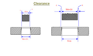
1: Clearance
The difference in dimensions between the mating members of a die set is called clearance. This clearance is applied in following manner:
1: when the hole has to be held to size i.e. the hole in the sheet metal is to be accurate (punching operation) , and slug is to be discarded. The punch is made to the size of the hole and the die opening size is obtained by adding clearance to the punch size.
2: In blanking operation , where the slug or blank is the desired part and has to be held to size, the die opening size equals the blank size and the punch size is obtained by subtract.

2: Cutting Forces
In cutting operation, as the punch in its downward movement enters the material, it need not penetrate the thickness of the stock in the order to offset complete rupture of the part. The distance which the punch enters into the work material to cause rupture to take place is called penetrable and is usually given as the %age of the stock thickness
The percent penetration depends on the material being cut and also on the stock thickness. When hard and strong material is being cut ,a very little penetration of the punch is necessary to cause feature. With soft material the penetration will be greater.
3: Strippers:
After a blank has been cut by the punch on its downward stroke, the scrap strip has the tendency to expand. On the return stroke of the punch the scrap strip has the tin deny to adhere to the punch and be lifted by it. This action interface with the feeding of the stroke through the die and some device must be used to strip the scrap material from the punch as it clears up the die block. Such a device is called “stripper” or stripper plate.
Stripper plate are of two types:
1: fixed or stationary
2: spring loaded or movable

(a): fixed or stationary strippers:
This stripper is attached at a fixed height over the die block. The height should be sufficient to permit the sheet metal to be fed freely between the upper die surface and the under surface of the stripper plate. The stripper plate thickness is determining by the formula:
Ts =1/8(w/3+16t)
Where w and t are width and thickness of the stock strip. The fixed stripper is also known as ‘channel stripper”
(b): Spring loaded Stripper:
This type is used on large blanking operations and also on very thin and highly ductile materials. As the punch travels downward for blanking operation the stripping force is determined with the help of following relation.          Fs=spt kn
Where p and t are in mm and s is the stripping constant.
 4:Pilots:-
Pilots are used in progressive dies. In the design of progressive dies, the first step is to establish the sequence of operations. In this sequence , the piercing operations are placed first. After the holes have been pierced , these holes are used for piloting the blanking punches so that the blank formed is truly concentric to the already punched hole. This piloting is achieved by means of pilots secured under the blanking punch. To be effective the pilot must be strong enough to align the stock without bending. Pilots are made of good grade of tool steel heat treated to maximum toughness and to a hardness of 56 to 60 Rockwell C.

Types of pilots: there are two types of pilots:
(a ): Direct pilot:
Pilots which are mounted on the face of a punch are called direct pilots. The pilot holder is generally a block of steel which can be fastened to the punch holder.
(b) Indirect pilot:
 Such pilots are well guided through the hardened bushes in the stripper plate.
5: Stock Stop:
The strip of sheet metal is fed and guided through a slot in the stock guide or through a slot in the stripper plate after each blanking. The strip has to be advanced a correct distance, the device used to achieve this is called “ stock stop”

Dies And Its Types

Dies and its Types:
Die:
The die may be defined as the female part of a complete tool for producing work in a press. It is also referred to a complete tool consists of a pair of mating members for producing work in a press.
Types of dies:
The dies may be classified according to the type of press operation and according to the method of operation.
(A): According to type of press operation:
According to this criterion , the dies may be classified as cutting dies and forming dies.
1: Cutting Dies:
These dies are used to cut the metal. They utilize the cutting or shearing action. The common cutting dies are : blanking dies , perforating dies , notching dies , trimming , shaving and nibbling dies.
2: Forming Dies:
These dies change the appearance of the blank without removing any stock. Theses dies include bending, drawing and squeezing dies etc.
(B) According to the method of operation:
According to this criterion, the dies may be classified as : single operation or simple dies , compound dies , combination dies , progressive dies , transfer dies and multiple dies.
1: Simple Dies:
Simple dies or single action dies perform single operation for each stroke of the press slide. The operation may be one of the operation listed under cutting or forming dies.
2: Compound Dies:
In these dies, two or more operations may be performed at one station. Such dies are considered as cutting tools since, only cutting operations are carried out. Figure shows a simple compound die in which a washer is made by one stroke of the press. The washer is produced by simulation blanking and piercing operations. Compound dies are more accurate and economical in production as compared to single operation dies.

3: Combination Dies:
In this die also , more than one operation may be performed at one station. It is difficult from compound die in that in this die, a cutting operation is combined with a bending or drawing operation, due to that it is called combination die.

4: Progressive Dies:
A progressive or follow on die has a series of operations. At each station , an operation is performed on a work piece during a stroke of the press. Between stroke the piece in the metal strip is transferred to the next station. A finished work piece is made at each stroke of the press. While the piercing punch cuts a hole in the stroke , the blanking punch blanks out a portion of the metal in which a hole had been pierced at a previous station. Thus after the first stroke , when only a hole will be punched , each stroke of the press produces a finished washer.

6: Transfer Dies:
Unlike the progressive dies where the stroke is fed progressively from one station  to another. In transfer dies the already cut blanks are fed mechanically from one station to other station.
7: Multiple Dies:
Multiple or gang dies produce two or more work piece at each stroke of the press. A gang or number of simple dies and punches are ganged together to produced two or more parts at each stoke of the press.

Types of Chips

Types of chips
The three common types of chip from a single point tool are.
 1;:Discontinuous or segmental chip:                         
Discontinuous chips is formed by a series of rupture occurring approximately perpendicular to the tool place face’ each chip element passing off along the tool face the chip  element’ in the form of small segment may adhere loosely to each other and becomes slightly longer. 
Since the chips break up into small segments the friction between the tool and the chips reduces’ resulting in better surface finish. These chips are convenient to collect’ handle and dispose off. Discontinuous chips tends to be formed when one or more or the following conditions exist:
1.     Brittle material , such as cast iron and bronze.
2.     large chip thickness
3.     low cutting speed
4.     small rack angle
Discontinuous chips are also produced when cutting more ductile material with the use of a cutting fluid.

2: Continuous Chips:
Continuous chips are formed by the continuous plastic deformation of metal without fracture in front of the cutting edge of the tool and is formed by the smooth flow of the chip  up the tool face. Mild steel and copper are considered to be most desirable materials for obtaining continuous chips. The chips obtained have same thickness throughout. This type of chip is the most desirable. Since it is stable cutting, resulting in generally good surface finish. On the other hand these chips are difficult to handle and dispose off.
Continuous chips tend to be formed when the following condition exist:
1.     ductile material
2.     high cutting speed
3.     small chip thickness
4.     large rack angle
5.     minimum friction of chip on tool face by :
·        polished tool face
·        use of efficient cutting lubricants.
·        Use of tool material with low-coefficient of friction.
3: Continuous Chip with Built up Edge:
This type of chip is very similar to the continuous chip. With the difference that it has a built up edge adjacent to tool face and also it is not so smooth. It is obtained by  machining on ductile material, in this condition of high local temperature and extreme pressure in the cutting and high friction in the tool chip interference, may cause the work material to adhere or weld to the cutting edge of the tool. Successive layers of work material are then added to the built up edge. When this edge becomes larger and unstable , it breaks up and part of it is carried up the face of the tool along with the chip while the remaining is left over the surface being machined, which contributes to the roughness of the surface. The built up edge changes its size during the cutting operation. It first increases , then decreases, then again increases etc.

Press working terminology

Press Working Terminology:
A simple cutting die used for punching and blanking operation as shown:

1: Bed:
The bed is the lower part of the press frame that serves as a table to which a
Bolster plate is mounted.
2: Bolster Plate:
This is a thick plate secured to the press bed , which is used for locating and
supporting the die assembly. It is usually 5 to 12.5 cm thick.
3: Die Set:
It is unit assembly which incorporates a lower and upper shoe, two or more guide parts and guide part bushings.
4: Die Block:
It is a block or a plate which contains a die cavity
5: Lower Shoe:
The lower shoe of the a die set is generally mounted on the bolster plate of a press. The die block is mounted on the lower shoe, also the guide post are mounted on it.
6: Punch :
This is male component of  a die assembly, which is directly or indirectly moved by and fastened to the press ram or slide.
7: Upper Shoe:
This is the upper part of the die set which contains guide post bushings.
8: Punch Plate :
The punch plate or punch retainer fits closely over the body of the punch and holds it in proper relative position.
9: Back up Plate:
Back up plate or pressure plate is placed so that intensity of pressure does
not become excessive on punch holder. The plate distributes the pressure
over a wide area and the intensity of pressure on the punch holder is reduced
to avoid crushing.
10: Stripper:
It is a plate which is used to strip the metal strip from cutting a non-cutting
Punch or die. It may also guide the sheet.

About This Site

Related Posts Plugin for WordPress, Blogger...
powered by Blogger | WordPress by Newwpthemes | Converted by BloggerTheme