Indirect extrusion

Indirect extrusion or backward extrusion
In order to completely overcome the problem, the backward hot extrusion as shown in figure, in this process the metal is confined fully by the cylinder, the ram which houses the die also compresses the metal against the container , forcing it to flow backward to the die in the hollow plunger or ram.
It is termed backward because of the opposite direction of the flow of the metal. Thus the billet in the container remains stationary and hence produce no friction. Also the extrusion pressure is not effected by the length. In the extrusion press since the friction is not loss. The figure of the backward extrusion is shown;


Direct extrusion or Forward extrusion

Direct Extrusion or Forward Extrusion
The equipment consists of a cylinder or container into which the heated metal billet is loaded. One end of the container, the die plate with necessary opening is fixed. From the other end plunger or ram compresses the metal billet against the container walls and die plate, thus the forcing it to flow of metal in the forward direction through the die opening.
Acquiring the shape of the opening the extruded metal is then carried by the metal is then carried b the metal handling system as it comes out of the die. A dummy block which is a steel disc of about 40mm thick with a diameter slightly less than container is kept between the hot billet and the ram to protect it form heat and pressure. In direct extrusion, the problem of friction prevalent because of the relative motion between heated metal billet and cylinder walls. To reduce this friction lubricants are to be used. To reduce the damage to equipment, extrusion is finished quickly and the cylinder is cooled before further extrusion.

extrusion processes

Extrusion Processes:
Extrusion is the process of confining the metal in a close cavity and then allowing it to flow from only one opening , so that the metal will take the shape of the opening. The operation is identical to the sequeezing of toothpaste out of the toothpaste tube.
By the extrusion process, it is possible to make component which have a constant cross section over any length as can be formed by the rolling process. Some typical parts can be extruded are shown:


Compexity of parts that can be obtain by extrusion is more than that of rolling, because the die required being very simple and easier to make. Also extrusion is a single pass process,unlike rolling the amount of reduction that si possible in extrusion is large. Generally brittle materials can be very easily extruded. It is also possible to produce sharp corners and different angles. It is possible to gets shapes with internal cavaties in extrusion by the use of spider die. Large diameters, thin walled , tubler products with execellent concentricity and tolerance charasitic can be produced.
Types of extrusion:
1: Direct extrusion or forward extrusion
2: Indirect extrusion or backward extrusion

Forging defects

Forging defects:
Though forging process give generally prior quality product compared other manufacturing processes. There are some defects that are lightly to come a proper care is not taken in forging process design.
A brief description of such defects and their remedial method is given below.
(A): Unfilled Section:
In this some section of the die cavity are not completely filled by the flowing metal. The causes of this defects are improper design of the forging die or using forging techniques.
(B): Cold Shut:
This appears as a small cracks at the corners of the forging. This is caused manely by the improper design of die. Where in the corner and the fillet radie are small as a result of which metal does not flow properly into the corner and the ends up as a cold shut.
(C): Scale Pits:
This is seen as irregular depurations on the surface of the forging. This is primarily caused because of improper cleaning of the stock used for forging. The oxide and scale gets embedded into the finish forging surface. When the forging is cleaned by pickling, these are seen as depurations on the forging surface.
(D): Die Shift:
This is caused by the miss alignment of the die halve, making the two halve of the forging to be improper shape.
(E): Flakes:
These are basically internal ruptures caused by the improper cooling of the large forging. Rapid cooling causes the exterior to cool quickly causing internal fractures. This can be remedied by following proper cooling practices.
(F): Improper Grain Flow:
This is caused by the improper design of the die, which makes the flow of the metal not flowing the final interred direction.

Forging operations

Forging operations:
1: Drawing:
This is the operation in which metal gets elongated with a reduction in the cross sedation area. For this, a force is to be applied in a direction perpendiaulant to the length axis.

2:Up setting:
This is applied to increase the cross seat ional area of the stock at the expanse of the length. To achieve the length of upsetting force is applied in a direction parallel to the length axis, For example forming of a bolt head.  


3:Fullering:
It a similar to material cross-section is decreased and length increased. To do this; the bottom fuller is kept in angle hole with the heated stock over the fuller .the top fuller is then kept above the stock and then with the sledge hammer, and the force is applied on the top fuller.  
                           
4:Edging:
It is a process in which the metal piece is displaced to the desired shape by striking between two dies edging is frequently as primary drop forging operation.


5:Bending:
Bending is very common forging operation. It is an operation to give a turn to metal rod or plate. This is required for those which have bends shapes.


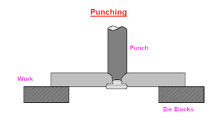
6:Punching:
It is a process of producing holes in motel plate is placed over the hollow cylindrical die. By pressing the punch over the plate the hole is made.


7:Forged welding:                                                                                                                                                       It is a process of joining two metal pieces to increase the length. By the pressing or hammering then when they are at for ging temperature.Itis performed in forging shop and hence is called forged welding.
8:Cutting:
It is a process in which a metal rod or plate cut out into two pieces, with the help of chisel and hammer, when the metal is in red hot condition.
9:Flating and setting down:
Fullering leaves a corrugated surface on the job. Even after a job is forged into shape with a hammer, the marks of the hammer remains on the upper surface of the job. To remove hammer marks and corrugation and in order to obtain a smooth surface on the job, a flatter or set hammer is used.


 10: Swaging:
Swaging is done to reduce and finish work for desire size and shape, usually either round or hexagonal. For small jobs top and bottom swage pair is employed, where as for large work swage block can be used.


Forging and its types

Forging and its types
Forging is the operation where the metal is heated and then a force is applied to manipulates the metals in such a way that the required final shape is obtained. Forging is generally a hot working process through cold forging is used sometimes.
Type of forging
1.     smith forging
2.     drop forging
3.     press forging
4.     machine forging
1: Smith forging
This is the traditional forging operation done openly or in-openly dies by the village black smith or modern shop floor by manual hammering or by the power hammer. The process involves heating the stock in the black smith hearth and then beating it over the anvil. To get the desire shape the operator has to manipulate the component in between the blows.
The types of operation available are fullering, flattering, bending , upsetting and swaging.
 2: Drop forging
Basic definition:
This is the operation done in closed impression dies by means drop hammer here the force for shaping the component is applied in a series of blows.
      
Drop forging utilizes a closed impression die to obtain the desire shape of the component , the shaping is done by the repeated hammering given to the material in the die cavity. The equipment use for delivering for blows are called drop hammers. The drop forging die consists of two halves. The lower halve of the die is fixed to the anvil of the machine , while the upper halve is fixed to ram. The heated stock is kept in the lower die, while the ram delivers 4-5 blows on the metal spreads and completely fills in the die cavity. When the two die of halves closed the complete is formed. The typical products obtained in drop forging are cranks, crank shaft, connecting rods, wrench, crane hooks etc. The types of operations are fullering, edging, bending, blocking , finishing and trimming etc.
3: Press forging
Similar to the drop forging , the press forging is also done in closed impression dies with the expectation that the force is continuous squeezing type applied by the hydraulic press. Press forging dies are similar to drop forging dies as also the process in press forging, the metal is shaped not by means of  a series of blows as in drop forging , but by means of a single continuous squeezing action. This squeezing is obtained by means of hydraulic presses. Because of the continuous action of by hydraulic presses, the material gets uniformly deform through out its entire depth ,the press forging dies with the various impression , such as fuller, bender and finisher impression properly arranged .
4: Machine forging:
Unlike the press or drop forging where the material is drawn out , in machine forging the material is only upset to get the desire shape. As it involves the upsetting operation some time it is simply called as upset forging. Originally this was develop for making bolts head in a continuous fashion, but now there are fairly large number of diverse.
Uses of this process:
Because of the beneficial grain flow obtain from upsetting. It is used for making gears, blanks, shafts, excels, and similar parts. Upsetting machine called up setter are generally horizontal acting. The die set consists of die and corresponding punch or a heading tool. The die consists of two parts, one called the stationary gripper die which is fixed to the machine frame and the other movable gripper die which moves along with the die slide of the up setter. The stock is held then between these two gripper dies.
The upset forging cycle start with the, movable die sliding against the stationary die to grip the stock. The two dies when in closed position from the necessary die cavity then the heading tool advance against the stock and upset it to completely filled to the die cavity.
Having completed the upsetting the heading tool moves back to its back position. Then the movable gripper die releases the stock by sliding backward. Similar to drop forging it is not possible to get the final shape in a single pass in machine forging also. Therefore the operation is carried out in number of stages. The die cavities is required for the various operations are all arrange vertically on the gripper dies. The stock is the move from stage one to another in proper sequence till the final forging is ready. A heading tool each for every upsetting stage is arranged on the heading slide of the upsetting machine. A typical upsetting die and heading tool is shown:


Types of rolling mills

                                          Types of Rolling mills
Rolling mills may be classified according to the number and arrangement of the rolls.
(a): Two high rolling mills
(b): Three high rolling mills
(c): Four high rolling mills
(d): Tandem rolling mills
(e): Cluster rolling mills
1: Two high rolling mills
 Two high rolling mills may further classified as
·        Reversing mill
·        Non reversing mill
A two high rolling mill has two rolls only.
Two high reversing mill:
In two high reversing rolling mills the rolls rotate ist in one direction and then in the other, so that rolled metal may pass back and forth through the rolls several times. This type is used in pluming and slabing mills and for roughing work in plate , rail , structural and other mills.


These are more expensive compared to the non reversing rolling mills. Because of the reversible drive needed.
Two high non reversing mill:
In two high non reversing mills as two rolls which revolve continuously in same direction therefore smaller and less costly motive power can be used. However every time material is to be carried back over the top of the mill for again passing in through the rolls. Such an arrangement is used in mills through which the bar passes once and in open train plate mill.


2: Three high rolling mill:
It consists of a roll stand with three parallel rolls one above the other. Adjacent rolls rotates in opposite direction. So that the material may be passed between the top and the middle roll in one direction and the bottom and middle rolls in opposite one.
In three high rolling mills the work piece is rolled on both the forward and return passes. First of all the work piece passes through the bottom and middle rolls and the returning between the middle and the top rolls.

So that thickness is reduced at each pass. Mechanically operated lifted tables are used which move vertically or either side of the stand. So that the work piece fed automatically into the roll gap.
Since the rolls run in one direction only a much less powerful motor and transmission system is required. The rolls of a three high rolling mills may be either plain or grooved to produce plate or sections respectively.
3: Four high rolling mill:
It has a roll stand with four parallel rolls one above the other. The top and the bottom rolls rotate in opposite direction as do the two middle rolls. The two middle are smaller in size than the top and bottom rolls which are called backup  rolls for providing the necessary rigidity to the smaller rolls.

A four high rolling mill is used for the hot rolling of armor and other plates as well as cold rolling of plates, sheets and strips.
4: Tandem rolling mills:
It is a set of two or three stands of roll set in parallel alignment. So that a continuous pass may be made through each one successively with change the direction of material.


5: Cluster rolling mills:
It is a special type of four high rolling mill in which each of the two working rolls is backup by two or more of the larger backup rolls for rolling hard in materials. It may be necessary to employ work rolls of a very small diameter but of considerable length. In such cases adequate of the working rolls can be obtained by using a cluster mill.


Cold working processes

 Cold working processes:
Below the recrystallization temperature if the mechanical work is done on the metals , there will no grain growth but it must be grain this integration elongation , the process is known is cold working processes. In cold working process greator pressure is required than that required in hot working. As the metal is in a more rigid state. It is not permanently deform until stress exceeds the elastic limit. Most of the cold processes are performed at room temperature , the different cold working processes are
1: Drawing
·        Wire drawing
·        Tube drawing
·        Blanking
·        Spinning
2:  Sequeezing
·        Coining
·        Sizing
·        Riveting
 3:   Bending
·        Angle bending
·        Plate bending
·        Roll forming
 4:  Shearing
      >Punching                >Blanking
           > Trimming               > Perforating
             >Notching                     >Launcing
                >Slittig
5:Extruding

Hot and Cold working processes


Hot and Cold working Processes:
The metal working processes are derived into hot working and cold working processes. The division is on the basis of the amount of heating applied to the metal before applying  the mechanical force. Those processes working above the re-crystallization temperature are hot working processes where as the below or termed as cold working processes.


Under the action of heat and force when the atom reach a certain high energy level the new crystal start forming , which is termed as re- crystallization. Re-crystallization destroys the old grain structure deform by the mechanical working and entirely new crystal which are strain free and form.
Re-crystallization temperature is defined as the approximate minimum temperature at which complete re-crystallization of a cold work metal occurs with in a specified time.
Hot working processes.
Hot working of metals takes place above re-crystallization by hot working processes the metal are given desired shape by subjecting then two forces which cause then to undergo plastic deformation at the temperature above the re-crystallization range.
Different hot working processes are as follows:
1: Forging
  • Hammer or smith forging
  • Drop forging
  • Upset forging
  • Press forging
  • Roll forging
  • Swaging
2: pipe welding
  • Butt welding of heated strips
  • Butt welding of electrical resistance
  • Lap welding
  • Hammer welding
3: Rolling
4: Piercing
5: Spinning
6: Extruding
7: Drawing or Cupping

Rolling

Rolling:
Rolling is a process where the metal is compressed between two rotating rolls for reducing its cross sectional area. This is one of the most widely use of all the metal working processes. Because of its higher productivity and low cost. Rolling would be able to produce components having cross sectional through out its length. May shape such as itl and channel section are possible , but not very complex shapes.
Rolling is normally a hot working process unless specifically mensions as cold working. The metal is taken into rolls by friction and subsequently compressed to obtain the final shape.
The thickness of the metal that can down into rolls depends on the roughness of the roll surface. Rougher rolls would be able to achive greator reduction than smoother rolls. The reduction that would be achieve with a given set of roll is designed as the angle of the bite. cold rolling is done bellow the recrystallization temperature of the metal , hot rolling is done when the metal pieces at uniform working temperature.

Difference between Hot and Cold Working processes

Difference between Hot rolling and cold rolling processes


                   Hot rolling
             Cold rolling
1: Metal is fed to the rolls after being heated above the recrytallization temperature.
1: Metal is fed to the rolls when it is below the recrystallization temperature.
2: In general rolled metal does not shows work hardening effect.
2: The metal shows the working hardening effect after being cold rolled.
3: Co-efficient of friction between two rolls and the stock is higher, it may even caused shearing of the metal in contact with rolls.
3: Co-efficient of friction between two rolls and the stock is comparatively lower.
4: Experiment measurement are difficult to make.
4: Experiment measurement can be carried out easily in cold rolling.

5: Heavy reduction in area of the work piece can be obtained.
5: Heavy reduction is not possible.
6: Mechanical properties are improved by breaking cast structure are refining grain sizes below holes and others, similar deformation in ingot (get welded) and or removed the strength and the toughness of the job should increases.
6: Hotness increased excessive cold working greatness crackers ductility of metal reduction. Cold rolling increased the tensile strength and yield strength of the steel.
7:Rolls radius is generally larger in siz.
7: Rolls radius is smaller.
8: Very thin sections are not obtained.
8:Thin sections are obtained.
9: Hot roll surface has(metal oxide) on it , this surface finish is not good.
9: The cold rolled surface is smooth and oxide free.
10: Hot rolling is used un ferrous as well as non ferrous metals such as industries for steel , aluminum, copper , brass, bronze , alloy to change ingot into slabs.
10: Cold rolling is equally applicable to both  plain and alloys steels and non ferrous metals and their alloys.
11: Hot rolling is the father of the cold rolling.
11: Cold rolling follows the hot rolling.


Shell Moulding

Shell  moulding ;
It is a process  in which the sand is mixed with a thermo setting resin is allowed to come into contact a heated metallic pattern plate ‘so that a them and strong shell of mould is formed around  the pattern’ then she is removed the pattern and the cope and drag are remove together and kept in a flask with the necessary back up material and the molten metal is pored into the mould.
Generally dry and fin sand which is completely free of the clay is used for preparing the shell mould in are the phenol formaldehyde rising combined with sand they hare very high strength and resistance through heat.


Steps  Involve;
Step 1;
A metal pattern having the profile of the required casting is heated to 180°-260°c in an own maintained at 300°-400°c pattern after being heated is taken out of the own and sprayed with a solution of a lubricating agent containing silicon. It is necessary to prevent the shell from sticking to the metal pattern.

Step 2:
Metal pattern(made up of iron or steel )is then turned faced down and clamped over the open end of the dump box.

Step 3:
the dump box is inverted so that dry sand raisin mixture falls on the face of hot metal pattern . the raisin the raisin softens and fuses to form a soft and uniform  sand mixture in contact with the pattern gets heat up .the   rasinsoftens and fuses to form a soft and uniform shell of about 6mm thickness on the surface of pattern.


Step 4;
As the dump box is turned to its original position. Excess sand resin mixture falls beak into the dump box leaving a shell adhering closely to the pattern


Step 5;
The shell is then stripped from the pattern plate with the help of ejector pins which are an integral part of the metal pattern 

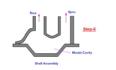
Step 6;
After the shells so obtained have cooled. Two meeting shell are securely fastened together to from a complete mould.


Sand Casting processes

Sand Casting Processes
For Case(A):
Bottom board is placed either boundary moulding from or on the floor making the surface even. The drag moulding flask is kept upside down on the bottom board. Dry facing sand is sprinkled over the board. Rest of the drag flask is completely filled with back up sand and uniform the rammed to compact the sand. The remaining of sand should be done properly. So as to compact it to hard , which makes the escape of gases difficult not to lose.
So that mould could not have enough strength . After the ramming is over , the excess of sand in the flask is completely scraped using a flat bar to the level of the flask edges. Now with a vent wire which is a wire of 1-2mm diameter with a pointed end, vent holes are made in the drag to he full depth flask as well as to the pattern to facilitate the removal of gases during casting solidification. This complete the preparation of the drag.

For  case  B:
We finished the drag flask is now rolled over to the bottom bolt exposing the pattern and cope of the pattern is placed over the dragged pattern.


For case C:
The cope flask on the top of the drag is rotated aligning again with the help of the pins. A screw pin for making the screw passage. The sand is thoroughly rammed and excess sand scrap and vent holes are made over all in the cope as in the drag.  The screw pin and the riser pin are carefully with drawn from flask  the mould is now ready.


manufacturing processes

Topic: Tool design(Mechanical Engineering)

Manufactuing Processes:
Introduction:
Manufacturing involves turning raw material to finished products, to be used for various purposes. There are a large number of processes available. These processes can be broadly classified into four categories.
1: Casting processes
2: Forming processes
3: Fabrication processes
4: Material removal processes
Casting Processes
These processes only processes where the liquid metal is used. Casting is also the oldest known manufacturing process.
Basically it consists of inducing the molten metal into a cavity of mould of the required form and allowing the metal to solidify.The object after solidification removed from the mould. Casting processes are universally used to manufacture a wide variety of products. Casting is the most flexible and cheapest method and given high strength of rigidity to the parts which are difficult to produce by other manufacturing processes.
The principle process among these sand casting where sand is used as the raw material. The process is equally suitable for the production of a small batch as well as on a large scale.Some of the other classified casting processes for specialized need are
·        Shell mould casting
·        Precision mould casting
·        Plaster mould casting
·        Permanent mould casting
·        Die casting
·        Centrifugal casting
Forming Processes:
These are solid state manufacturing processes involve minimum amount of material wastage. In forming process metal may be heated to temperature which is slightly below. This solidify temperature and large force is applied such the material flows and act in desired shape. The desire shape is controlled by means of a set of tool  ties and dies, which may be closed during manufacturing.
These processes are normally used for large scale production rates. These are generally economical and in many cases improve the mechanical properties. These are some of the metal forming processes.
·        Rolling forging
·        Drop forging
·        Press forging
·        Upset forging
·        Extrusion forging
·        Wire forging
·        Sheet metal operation
Fabrication Processes
These are secondary manufacturing processes where the starting raw materials are produced by any one of the previous manufacturing processes desired. Its assembly involve joining pieces either temporary or permanent. So that they would be perform the necessary function. The joining can be achieved by either or both of heat and pressure joining materials.
Many of the steel structure construction, we see are first rolled and then joined together by a fabrication process are
·        Gas welding
·        Electric arc welding
·        Electrical resistance welding
·        Thermo welding
·        Brazing welding
·        Soldering welding
·        Cold welding
Material removal processes:
   These are also a secondary removal manufacturing process, where the additional unwanted material is removed in the form of chips from the blank material by a hard tools so as to obtained the final desired shape.
Material removal is normally a most expensive manufacturing process. Because more energy is consumed and also a lot of waste material is generated in this process. still this process is widely used because it deliver very good dimensional accuracy and good surface finished. Material removal process are also called machining processes. Various processes in this category are
·        Turning
·        Drilling
·        Shaping and planning
·        Milling
·        Grinding
·        Broaching
·        Sawing
·        Trimming

About This Site

Related Posts Plugin for WordPress, Blogger...
powered by Blogger | WordPress by Newwpthemes | Converted by BloggerTheme