

Elements of Jigs and Fixtures
 6:52 PM
 , Posted in
Elements of Jigs and Fixtures.
Various elements of jigs and fixtures and their details are follows.
1: Body 2: Locating devices
3: Clamping devices
4: Tool guide(jigs bushing)
1: Body:
The jig body is generally made of cost iron by casting process or fabricated by welding together various slabs and bars of mild steel. It may be heat treated to relief the stresses. Body is the most prominent feature of the jig. Its main purpose is to support and house the job.
The various jig body are follows:
(A):Plane Type Jig:
Plane type jig is the simplest type, it is used when plane holes are to be drilled. It has either drill bushes for guiding the tools or the holes without bushes.
(B): Channel Type Jig:
Channel type is made up from standard steel channel section.
(C): Box type Jig:
Box type jig is used where a component requires drilling in more than one plane and the jig is to be provided with on equilant number of drill bush plates. One side of the box is fitted with a lid which can be opened for inserting the component and for unloading it. It should be made as light as possible.
(D): The Built Up Jig:
The built up jig used dowels and screws for fabricating member welded type. Standard steel sections are used in it for the limited numbers of details, which are secured by means of screws and dowels, the locating pins and the blocks are positioned so that the greatest dimensional variation of the work piece may be accommodated.
(E): Leaf Type Jig:
Leaf type jig is simple made from a block of steel fitted with two adjustable locating screws and a spring loaded plunger. It is used in case of measured large components where it may be both unnecessary and construct a jig to hold the complete component , where madding is purely confined to a local section of the work piece.
2:Locating Devices
The pins of various design and made of hardened steel are the most common locating devices used to locate a work piece in a jig or fixture. The shank of the pin is press fitted or driven into the body of jig or fixture. The locating diameter of the pin is made larger than the shank to prevent it from being forced into the jig or fixture body due to the weight of the work piece or cutting forces. Depending upon the mutual relation between the work piece and the pin.
The pin may be classify as follows:
(A): Locating Pins:
When reamed or finally finished holes are available in work piece, these can be used for locating purpose of the manner as shown , these are two types of locating pins:


· Conical locating pins
· Cylindrical locating pins
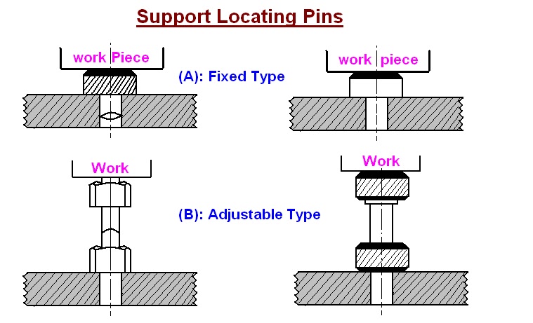
(B): Support Locating Pins:
With these pins (also known as rest pins) buttons or pads the work piece with flat surfaces supported at convenient. In the fixed support pins the locating face is either ground flat or curved. Support pins with flat head are usually employed and provided location and support to machine surface, because more contact area is available during location. It would insure accurate and stable location. The spherical head or round head rest buttons are used for supporting rough surfaces (un machined and cast surfaces) because they provide a point support which may be stable under these circumstances. Adjustable type support pins are used for work piece whose dimension can vary. For example sand casting, forging or unmachined faces.

(C): Jack Pins:
Jack pins or spring pins are also used to locate the work piece whose dimension are subjected to variation. The pin is allow to come up under spring pressure or conversely is pressed down by the work piece. When the location of the work piece is secured the pin is locked in this position by means of locking screw.


Elements of jigs and fixtures:
3: Clamping devices:
If the work piece can not be restrained by the locating devices or elements, it become necessary to clamp the work piece in jig or fixture body. The most common example of clamping devices is bench vice. The purpose of the clamping is to exert a pressure to press a work piece against the locating surfaces and hold it there in a position to the cutting forces. In bench vice the movable jaw of the vice exert force on the work piece , their by holding it in correct position of location in the fixed jaw of the vice.
The commonly used clamping devices are follows:
(A): Clamping Screws:
Clamping screws are used for light clamping. Clamping screws are shown in fig.


(B): Hook Bolt Clamp:
This is very simple clamping device and is only suitable for light work and where usual tip of the clamp is inconvenient. The typical hook bolt clamp is shown.


(C): Bridge Clamp:
It is very simple and reliable clamping device. The clamping force is applied by spring loaded nut.


(D): Heel Clamp:
These consists of a rusted plate, center stud and heel. This trap should be strengthen at the point where the hole for the stud is cut out, by increasing the thickness around the hole. The design differ from simple bridge clamp in that a heel is provided at the outer end of the clamp to guide its sliding motion for loading and unloading the work piece.

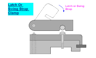
(E): Swinging Strap(Latch Clamp):
This is a special type of clamp which provides a means of intry for loading and unloading the work piece. For this the strap(latch or lid) can be swing out from the work piece. The typical swing strap or latch clamp is shown in figure.

(F): C-Clamp:
To unload the work piece, the locking nut is unscrewed by giving it about one turn and this releases the c- clamp. When the clamp is removed or swing away the work piece can freely pass over the nut. To reverse procedure is adopted for loading the work piece.


>: Element of jigs and fixtures:
4: Tool Guide or Jig Bushing:
Sometimes the stiffness of the cutting tool may be in sufficient to perform certain machining operations. Then to locate the tool relative to the work, use is made of guiding parts such as jigs bushing and templates. These must be precise, were resistance and changeable.
Jig bushes are used in drilling and boring, a bush fits into the hole of the jig, through which the drill passes. The diameter of the bush depends on the diameter of the drill. Different type of bushes are spot welded or screwed with the jig. Headless type bushes are press fit into the hole of the job. Bushes are general made of a good grade of tool steel to insure hardening at a fairly no temperature and to lesson the danger of fire cracking. Sometime the bushes for guiding tools may be of cast iron. Hardened steel bushes are always preferable for guiding drills, reamers and taps etc.
American standard bushes are classified in three categories.
1: press- fit wearing bushes
2: renewable wearing bushes
3: linear wearing bushes
Types of bushes (tool guide/jig bushes):
1: Press fit wearing bushes:
These bushes are used when little importance in put on accuracy or finish and tool used is a twist drill. These bushing are installed directly in the jig body and are used mainly for short protection. There are two design of press fit bushing:

A> Plain or headless bush
B> Headed or flanged bush
2: Renewable bushes:
When the guide bushes requires periodic replacement (due to wear of the inside diameter of the bush). Its replacement is simply by using a renewable bush. These are of the flanged types and sliding fit into the linear bush, which is installed press fitted into the jig plate. The linear bush provides hardened wear resistance, mating surface to the renewable bush. The renewable bushes must be prevented from rotating or lifting with the drill. One common method is to use a retaining screw.


3: Linear bushes:
These bushes are also known as master bushing, are permanently fixed to the jig body. These acts as guides for renewable type bushing. These bushes are be with or without head.

